leds have some benefits over other lighting, blah blah blah, i will not discuss them here, if you are reading this you most likeley already know. one of the major costs of led projects is the driver, up to 50% of the cost of leds in some cases. you can build a transistor based driver in order to cut down a large part of the cost without sacrificing the lifespan of your leds.
why regulate?
leds are very sensitive to changes in voltage, the difference in 1 volt is the difference between not having enough power to turn on and overpowering it.
to throw in another curveball, the amount of current they draw based on voltage (you can think of this as brightness) varies between leds of the same kind and also varies with the temp. also the alignment of the planets and the day of the week.
thus, leds need to be driven by providing them a constant current (via some kind of regulation )instead of a constant voltage, high powered leds, commonly referred to as 3 watt leds tend to be able to withstand 700-1000 milliamps(ma) max (cheap led manufacturers tend to skip this and drive from voltage without going through a constant current regulator)
small 5mm leds such as keychain flashlights and moonlights are 20-30 ma max usually, also they are very ineffecient and in large numbers like you see in cheap led panels on ebay, heat each other up and shorten lifespan.
alright on to the driver
thanks to dan over at instructables for coming up with this idea
the real source:
http://www.instructables.com/id/Power-LED-s---simplest-light-with-constant-current/
also thanks to evilc66 for answering endless questions for me
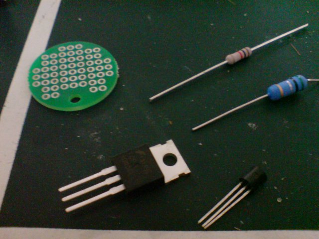
parts, fet transistor (big square one), npn transistor (small 3 pin dealie), large resistor (100k ohm), current set resistor (current set by .5/ohms)the large resistor i am referring to here is the grey one, in size it is actually smaller than the current set
the current set resistor here is important, getting one that is .5 ohms will set the current to 1000ma or 1 amp, that should be the absolute max to set it to. if you want 700ma (my recomendation for medium sized tanks) then you would get a resistor of about .7 ohm, .68 ohm resistors are a little more common i think.
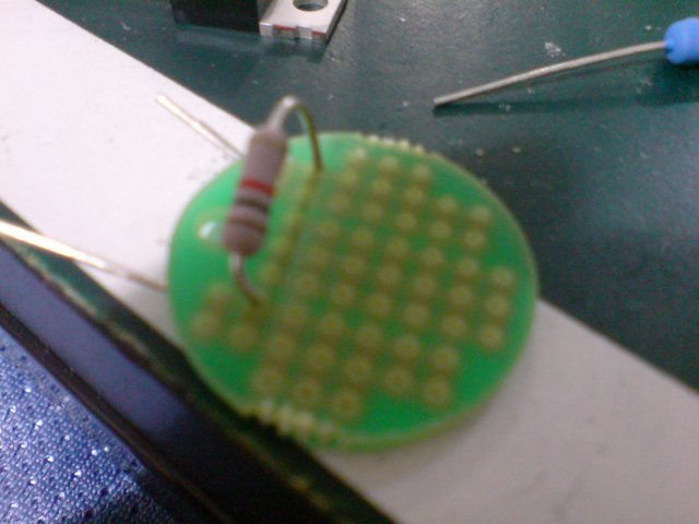
step 1: place the large resistor on the left side of the board, the end of the resistor closest to you is where you will attach two wires for led positive and power supply positive
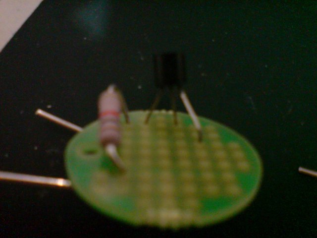
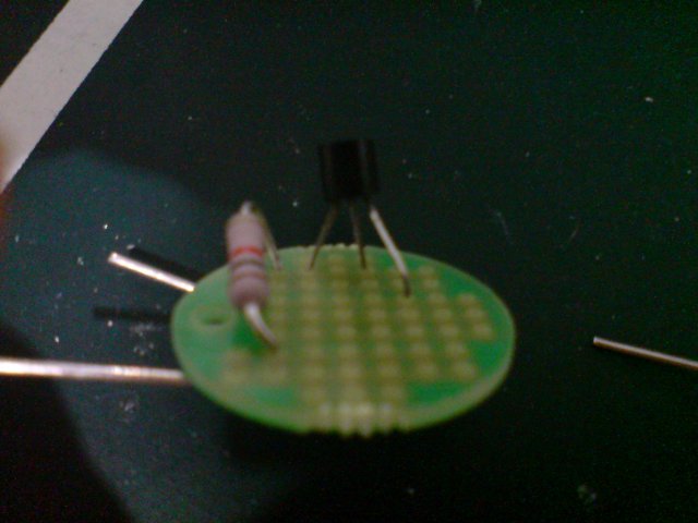
step 2: place the npn transistor, face the round end towards yourself, place the left most pin in a hole where you can connect it to another pin behind it and the other lead of the large resistor. the middle pin should skip a hole to the right and the right pin should go foreward a couple of holes and to the right
step 3: put the fet transistor down behind the npn transistor, the left lead should be able to connect to the left leg of the npn transistor and the resistor ( 3 things to connect by solder ) the middle leg of the fet transistor should line up with the empty hole you left when you set the npn transistor down. this leg is the led negative. the right leg of the fet should line up with the middle leg of the npn
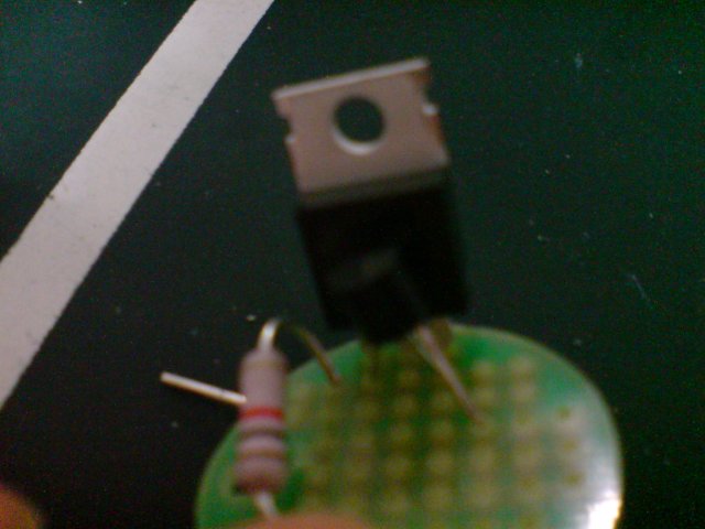
step 4: use the current set resistor to connect the right leg of the fet and middle leg of the npn to the right leg of the npn(which you bent foreward a couple of holes) the right leg of the npn which is now connected to the current set resistor is the power supply negative
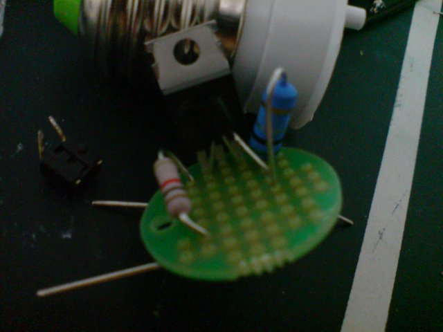
attach a small heatsink (such as a ram heatsink) to the back of the fet, be careful because it is now eletrically charged
review:
so now there should be 3 connections
the left side: 1 end of the big resistor+left leg of npn+left leg of fet
the right side: 1 end of current set resistor+ middle leg of npn + right leg of fet
the front side ther end of current set resistor+right leg of npn
you can make a big blob of solder on each of those connections, just make sure they dont accidentally touch the middle leg of the fet.
the connection points are:
led positive: the other end of big resistor
led negative: middle leg of fet
power supply (power in) positive: other end of big resistor (come from the same point as led positive)
power supply negative: the front side connection
okay i built this foolish thing now what?
select a power supply
add up the foreward voltage of the number of leds you want per string (a realistic number here is 2-12) you will need 1 driver per string, for instance 6 leds(cree xr-e) @ 700ma is 6*3.5(gotten from the datasheet) which equals 21. the driver needs .5v to operate on, i suggest giving it 1v for saftey so get a 22v power supply here.
you can go higher, but not lower, for the 6 leds here you will more easily find a 24v power supply, so now the driver has to deal with an extra 2.5v, it is slightly less effecient now since it has to blow that power off.
in order for this driver to be used effeciently you need to have the voltage as close to (22 in this case) the required voltage as possible.(22 in this case)
the current rating of the power supply needs to be over the current per driver*number of drivers. for instance if you are running 3 drivers of 700ma you will need a 2.1A power supply at least, definateley do not push the upper limit of your power supply, i dont like to use more than 75% of the current rating.
so now i have a power supply and drivers
connect your drivers in parallel and connect them to the power supply accordingly
from the driver, connect your string of leds in series
whip out the sunglasses and plug in once youve triple checked everything ( the main cost of your led project will depend on the thoroughness of your checking) run your multimeter in series with any of the led strings to check the current (treat the multimeter like another led)
leds need to be heatsinked and kept cool, some people have experimented with alternitives (myself included) i have tried .19 inch thick aluminum with heatsinks stuck to the back, i have seen aluminum bars and square pipes. the key here is to use aluminum (copper is better but much more expensive) because it is a good conductor of heat. the cooler your keep your leds the longer they will last, sometimes you will need a fan, especially if you are building a fixture for a reef because of the density of leds needed.
there are a few methods of attaching leds to a "heatsink" the best method is drilling and tapping, drill holes in the heatsink and tap them so they can accept a #4 screw, use these to hold the leds down and put a thin layer of heat transfer compound between the led star and the heatsink.
there are also thermal pads that are sticky on both sides that you can use to attach your led to the heatsink. there is thermal epoxy, arctic silver makes one and its basicly a glue that you mix together that will allow you to stick the led to the heatsink ( pressure while the glue is setting is key)
im sorry i am not the best writer nor the best explainer, questions comments suggestions welcome




why regulate?
leds are very sensitive to changes in voltage, the difference in 1 volt is the difference between not having enough power to turn on and overpowering it.
to throw in another curveball, the amount of current they draw based on voltage (you can think of this as brightness) varies between leds of the same kind and also varies with the temp. also the alignment of the planets and the day of the week.
thus, leds need to be driven by providing them a constant current (via some kind of regulation )instead of a constant voltage, high powered leds, commonly referred to as 3 watt leds tend to be able to withstand 700-1000 milliamps(ma) max (cheap led manufacturers tend to skip this and drive from voltage without going through a constant current regulator)
small 5mm leds such as keychain flashlights and moonlights are 20-30 ma max usually, also they are very ineffecient and in large numbers like you see in cheap led panels on ebay, heat each other up and shorten lifespan.
alright on to the driver
thanks to dan over at instructables for coming up with this idea
the real source:
http://www.instructables.com/id/Power-LED-s---simplest-light-with-constant-current/
also thanks to evilc66 for answering endless questions for me
parts, fet transistor (big square one), npn transistor (small 3 pin dealie), large resistor (100k ohm), current set resistor (current set by .5/ohms)the large resistor i am referring to here is the grey one, in size it is actually smaller than the current set
the current set resistor here is important, getting one that is .5 ohms will set the current to 1000ma or 1 amp, that should be the absolute max to set it to. if you want 700ma (my recomendation for medium sized tanks) then you would get a resistor of about .7 ohm, .68 ohm resistors are a little more common i think.

step 1: place the large resistor on the left side of the board, the end of the resistor closest to you is where you will attach two wires for led positive and power supply positive

step 2: place the npn transistor, face the round end towards yourself, place the left most pin in a hole where you can connect it to another pin behind it and the other lead of the large resistor. the middle pin should skip a hole to the right and the right pin should go foreward a couple of holes and to the right

step 3: put the fet transistor down behind the npn transistor, the left lead should be able to connect to the left leg of the npn transistor and the resistor ( 3 things to connect by solder ) the middle leg of the fet transistor should line up with the empty hole you left when you set the npn transistor down. this leg is the led negative. the right leg of the fet should line up with the middle leg of the npn

step 4: use the current set resistor to connect the right leg of the fet and middle leg of the npn to the right leg of the npn(which you bent foreward a couple of holes) the right leg of the npn which is now connected to the current set resistor is the power supply negative

attach a small heatsink (such as a ram heatsink) to the back of the fet, be careful because it is now eletrically charged
review:
so now there should be 3 connections
the left side: 1 end of the big resistor+left leg of npn+left leg of fet
the right side: 1 end of current set resistor+ middle leg of npn + right leg of fet
the front side
you can make a big blob of solder on each of those connections, just make sure they dont accidentally touch the middle leg of the fet.
the connection points are:
led positive: the other end of big resistor
led negative: middle leg of fet
power supply (power in) positive: other end of big resistor (come from the same point as led positive)
power supply negative: the front side connection
okay i built this foolish thing now what?
select a power supply
add up the foreward voltage of the number of leds you want per string (a realistic number here is 2-12) you will need 1 driver per string, for instance 6 leds(cree xr-e) @ 700ma is 6*3.5(gotten from the datasheet) which equals 21. the driver needs .5v to operate on, i suggest giving it 1v for saftey so get a 22v power supply here.
you can go higher, but not lower, for the 6 leds here you will more easily find a 24v power supply, so now the driver has to deal with an extra 2.5v, it is slightly less effecient now since it has to blow that power off.
in order for this driver to be used effeciently you need to have the voltage as close to (22 in this case) the required voltage as possible.(22 in this case)
the current rating of the power supply needs to be over the current per driver*number of drivers. for instance if you are running 3 drivers of 700ma you will need a 2.1A power supply at least, definateley do not push the upper limit of your power supply, i dont like to use more than 75% of the current rating.
so now i have a power supply and drivers
connect your drivers in parallel and connect them to the power supply accordingly
from the driver, connect your string of leds in series
whip out the sunglasses and plug in once youve triple checked everything ( the main cost of your led project will depend on the thoroughness of your checking) run your multimeter in series with any of the led strings to check the current (treat the multimeter like another led)
leds need to be heatsinked and kept cool, some people have experimented with alternitives (myself included) i have tried .19 inch thick aluminum with heatsinks stuck to the back, i have seen aluminum bars and square pipes. the key here is to use aluminum (copper is better but much more expensive) because it is a good conductor of heat. the cooler your keep your leds the longer they will last, sometimes you will need a fan, especially if you are building a fixture for a reef because of the density of leds needed.
there are a few methods of attaching leds to a "heatsink" the best method is drilling and tapping, drill holes in the heatsink and tap them so they can accept a #4 screw, use these to hold the leds down and put a thin layer of heat transfer compound between the led star and the heatsink.
there are also thermal pads that are sticky on both sides that you can use to attach your led to the heatsink. there is thermal epoxy, arctic silver makes one and its basicly a glue that you mix together that will allow you to stick the led to the heatsink ( pressure while the glue is setting is key)
im sorry i am not the best writer nor the best explainer, questions comments suggestions welcome


