I am about 95% done with this project now. I got the relay circuit to control the drain pump done yesterday, and the holder for the float switches.
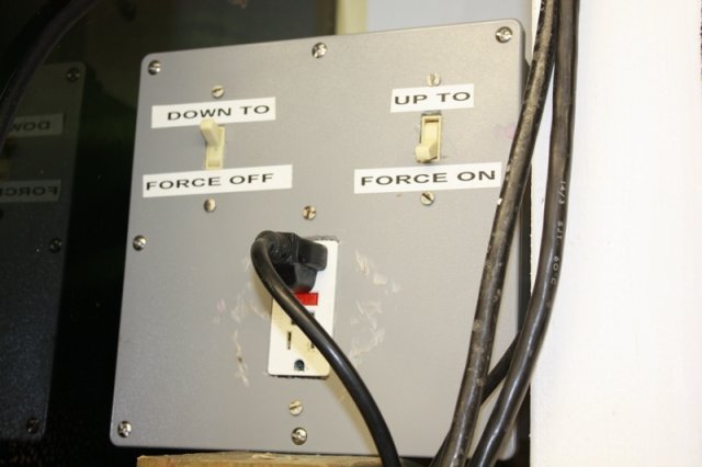
The box holds a relay, the two override switches and a GFCI plug. Coupled with the two float switches in the sump, this controls the pump's power. The water is constantly added to the sump. It rises until it trips the upper float switch. This kicks on the pump, which starts draining the sump. It drains until the lower float switch opens, then that trips the relay and turns off the pump. Big thanks to wesleydnunder for giving me a bunch of help designing the control circuit.
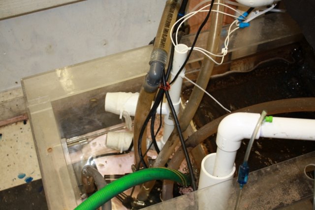
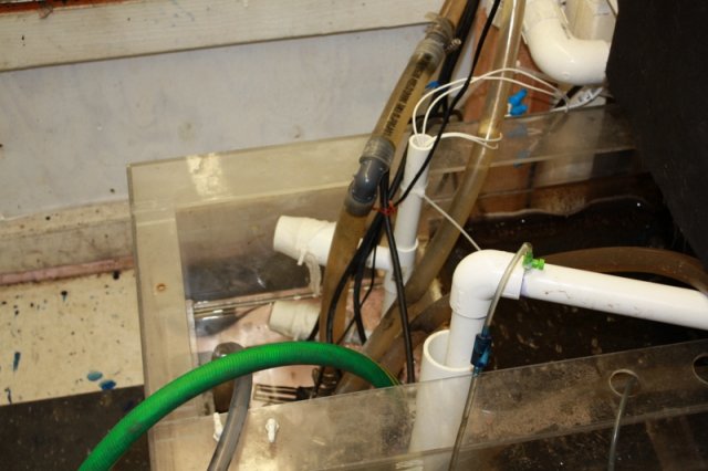
The float switches are actually pretty small, but I built bell housings around them to keep turbulence from tripping them prematurely, and also to keep snails out of the switches.
As stated in the picture, the two override switches in the box can either force the pump to be on or off regardless of float switch position.
The only real part left is to buy the fitting to go from garden hose thread to a 1/4" slip tubing so I can hook up the hose that will be the auto drip part. The only other improvement I might do is instead of having this drip directly into the sump, I might put a mechanical float valve high up so if for some reason both switches fail and the water level gets too high, the mechanical switch will prevent the sump from overfilling. I also should raise the draining pump off the sump floor an inch or so, so if again, for some reason if both floats fail and the pump just keeps draining, it only burns out one pump instead of all five. Anyway, I'm just happy to have it functioning.


