1. The Basics
Ok, so you might have heard of numerous HO (Hight Output) LED projects that are going around in the aquarium hobby, and the commercial HO LED products as well for the marine side. If you are not as inclined to electronics as some other people, you are probably asking "whats all the hub-bub, bub?)
Simple, HO LED lighting is more energy efficient than any fluorescent fixture out there, including T-5's. They also include several benefits.
So, what is an LED?
A: The LED (Light Emitting Diode)
An LED is simple, its a diode that emits light when current flows through it. But what is a Diode? A diode is a solid-state device that kind of acts as electrical check valve, allowing electricity to flow in one direction and one direction only. LEDs act the same way, which is why they require Direct Current to operate correctly.
LEDs also come in may different colors, red, blue, green, orange, yellow, purple, pink and various shades of white.
However, as mention before, they are very expensive right now compared to other lighting methods, or at least the upfront cost is. LEDs really shine in how long they last. If proper cooling methods are observed, your LED fixture could last 10-15 years. When you compare the costs of replacing your PC and T5 tubes over a 10 year period, it really adds up.
B: Electrical Terms.If you do decide to build your own LED systems, there are a few terms you should be familiar with
B: Required tools.
Sadly, tools are needed in this project. Most are simple.
2. Designing the LED array.
Sadly, it takes planning to correctly DIY your own high power LEDs. First thing is first though. We need a hood or canopy. You should probably build this first, then plan your array. Wood is always a good choice, its easy to work with, and you can make alot of nice designs. I believe a number of schematics are floating around the web.
Ok, So, now that thats out of the way, whats next? Decide on a good number of HO LEDs to light your tank. A good number to start with is about 1 per 24 square inches of surface area for a medium-high light tank, Increase/decrease the number to fit what you want. Just know that playing with the number will not have much of an effect as to algae growth. Algae does really bad under LED lighting, unknown why at this time. Also, quick side note, I suggest the Luxeon Rebel LEDs pre-mounted to a star base found here.
PLEASE NOTE: This rule of thumb does not work for hex tanks. HO LEDs generally shine light in a pretty focused area.
So lets say you have a 30g tank, you want say, 20... good number, lots of light. You may want to round up/down depending on your power supply)
So next step, Power supply, or PSU (Power Supply Unit) to convert that 110AC (220 for you accross the pond) into DC power.
This site sells quite a few power supplys
Ok, so what kind of voltage will we need, up to you really. The more volts you have, the less amps will be required. 12-24v is usally a good number. a 12v array can have 3 LEDs per series circuit, a 24v can double that to 6. But all in all, I recommend a 12v system, mainly because its easier to round so you don't waste power. A cheap solution is to convert a computer PSU, just beware, most will not supply exactly 12v, some may be 11. Use a DVM to test it first. There are various instructables on how to do this.
Well, now we have a hood, our LEDs, and the powersupply. Now we need drivers, You have various ways of doing this.

Hood: Check. LED's: Check. PSU: Check. Driver: Check. Now what? HEATSINKS!. This is probably going to be the most difficult part to round up. Ebay has a few large heatsinks, another two sites offer these.
Good option.
Better option, though more expensive.
Please, do be aware that fans are required. with just three on a small heatsink and no air movement, temp reached 160F after a single hour. A minimum of one fan is required, and it must have a good flow. Even a little flow though can cool it down quite a bit. Decent fans can be salvaged from computers. New fans can be aquired localy (though costing an arm and a leg) or better yet, through Newegg.com.
Ok, now I think we have everything. Now to get started :dance:
3. Attaching LED's to the Heatsink.
Ok, so we have the LED's and the HS, now to attach them. Two ways to do this. Drill and tap #4 screw holes or use a thermal epoxy. Both are semi-good solutions. Option one requires the purchase of a #4 tap bit and the drill bit. It will also require the use of a drill press, and a thermal compound (Artic Silver 5 is the best you will find, sold at Radio Shack and Newegg.). So, not cheap nor easy, but it does allow you to remove the LED should the need arise. Option 2 is basicly a glue that conducts heat extremely well. But will usually run about $20-$30, also be aware that it is very very permanent. But easy.
Option One Instructions: Use masking tape to tape the LEDs to where you want them on the heatsink. Then with a drill press, drill the holes to where you want screws, two per LED is fine. Once the holes are drilled, use the tap along with oil (any oil, I used power steering fluid, it was on hand) to tap out the holes. Once that is complete, apply a small bead of AS5 to the center of the star, then screw in the retaining screws to hold it secure. The pressure will force the AS5 outward and make a good thermal conduit.
DO NOT remove the LED to check the application. This will trap air inside. If you do wish to check, wipe off the old compound and reapply.
Option Two: Read and follow instructions that came with the epoxy.
4. Wiring the LED
So, time wire up the LED's, but how, which wire goes where? I know, confusing.
There are two types we are going to be dealing with, a single mounted LED and a triple mounted LED.
Lets start with the single LED per star should you have this version.
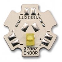
Notice the 6 solder points marked with - and +. To wire this one, the positive is on the right of the LED, and negative is on the left of the LED. When wiring in series, the negative of the previous LED attaches to the positive of the next LED.
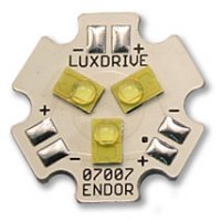
Now for the triple mounted, I believe that this one should have two SMD (Surface Mount Device) 0 ohm resistors across four of the power terminals. If this is the case then simply wire the ones that don't have that resistor. If they dont' then you will have to wire them in series yourself.
Caution: If you have soldered before, throw those rules out the window with these. About the only thing that will stick is the flux. To make a good connection, use a solder containing silver. Standard lead/tin does not work well with this method.
Heat the wire up and apply the silver solder, get a good coat of solder on the wire (also called tinning). Then heat the wire terminal of the LED, apply a small coat of solder to that pad. Now, place the tinned wire on top of the tinned terminal, apply the heat to wire, ensure solder on both the wire and the pad has melted, keep heat applied for 5 seconds after initial melting and then remove. When you remove the heat source, be sure to keep the wire in place. The wire should now be soldered.
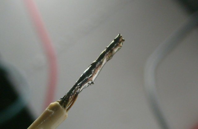
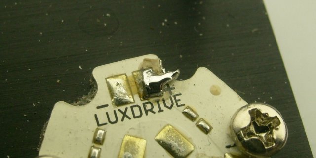
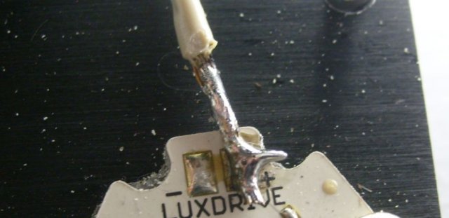
Your finished product should look like this.
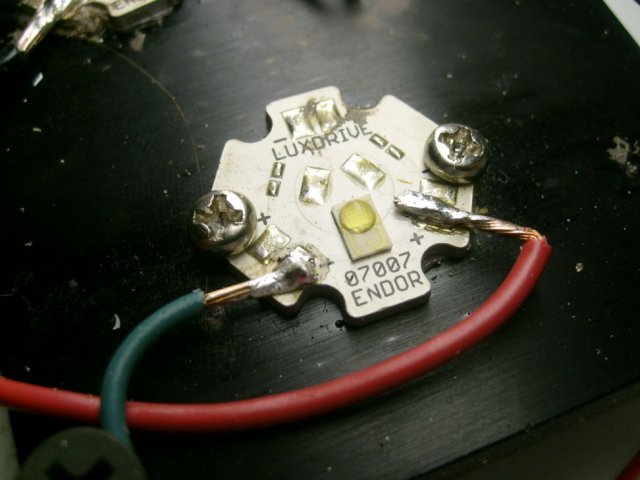
The reason for the use silver solder is because standard lead/tin solder does not like re-heating, and becomes very difficult to work with after the initial solder.
All that is left is to connect the wires up to our driver, and we are done :dance:
Make sure you connect your drivers correctly. All that is left to do is to do a power up test. This is where your DVM comes into play. Verify that you are getting 700mA out of each circuit, if you are not, just PM me if you need any troubleshooting help.
BTW, if a mod would add this to list of DIY links, I'd be very grateful.


Ok, so you might have heard of numerous HO (Hight Output) LED projects that are going around in the aquarium hobby, and the commercial HO LED products as well for the marine side. If you are not as inclined to electronics as some other people, you are probably asking "whats all the hub-bub, bub?)
Simple, HO LED lighting is more energy efficient than any fluorescent fixture out there, including T-5's. They also include several benefits.
- Low voltage.
- Various colors.
- Fully dimmable.
- Small and compact.
- Grows better plants than most fluorescent fixtures.
- Provides a neat shimmer effect.
- Require DC (Direct Current).
- Require a current limiting device
- Require special thermal considerations.
- Expensive, typical setups could run $100-$500 depending on size of the tank and amount of light needed. &1,500+ for commercial setups.
So, what is an LED?
A: The LED (Light Emitting Diode)
An LED is simple, its a diode that emits light when current flows through it. But what is a Diode? A diode is a solid-state device that kind of acts as electrical check valve, allowing electricity to flow in one direction and one direction only. LEDs act the same way, which is why they require Direct Current to operate correctly.
LEDs also come in may different colors, red, blue, green, orange, yellow, purple, pink and various shades of white.
However, as mention before, they are very expensive right now compared to other lighting methods, or at least the upfront cost is. LEDs really shine in how long they last. If proper cooling methods are observed, your LED fixture could last 10-15 years. When you compare the costs of replacing your PC and T5 tubes over a 10 year period, it really adds up.
B: Electrical Terms.If you do decide to build your own LED systems, there are a few terms you should be familiar with
- Volts
- Amps (or Current)
- Resistance
- Ohm's Law
- Kirchoff's Law
- Digital Multi-meter
- Soldering Iron
- Volts is basically electrical pressure, Often referred as the symbol E.
- Amps refers to how much current is flowing through, think water flow, Often referred as the symbol I
- Resistance is pretty simple, resistance. Often referred as the symbol R
- Ohm's Law is pretty simple, E(volts)=I(current, amps) X R(resistance) or for power calculations (watts) P(power)= E X I.
- Kirchoff's Law states that in a series circuit, Voltage divides, current remains the same at all points in the circuit. In a Parallel circuit, voltage remains constant and current divides.
- A DVM is a device which can measure Volts, current and resistance, essential.
- A soldering iron is like a hot glue gun, but instead we melt metal with it to form good connections.
B: Required tools.
Sadly, tools are needed in this project. Most are simple.
- 25-35w Soldering iron.
- Soldering containing silver (explained in section 5).
- Drill or Drill press (DP preferred, both optional).
- Wire cutters.
- Wire strippers.
- Wire Crimper.
- Screwdriver (optional).
- Electrical tape (ok, not a tool, but useful).
- Digital multi-meter (or DVM)
2. Designing the LED array.
Sadly, it takes planning to correctly DIY your own high power LEDs. First thing is first though. We need a hood or canopy. You should probably build this first, then plan your array. Wood is always a good choice, its easy to work with, and you can make alot of nice designs. I believe a number of schematics are floating around the web.
Ok, So, now that thats out of the way, whats next? Decide on a good number of HO LEDs to light your tank. A good number to start with is about 1 per 24 square inches of surface area for a medium-high light tank, Increase/decrease the number to fit what you want. Just know that playing with the number will not have much of an effect as to algae growth. Algae does really bad under LED lighting, unknown why at this time. Also, quick side note, I suggest the Luxeon Rebel LEDs pre-mounted to a star base found here.
PLEASE NOTE: This rule of thumb does not work for hex tanks. HO LEDs generally shine light in a pretty focused area.
So lets say you have a 30g tank, you want say, 20... good number, lots of light. You may want to round up/down depending on your power supply)
So next step, Power supply, or PSU (Power Supply Unit) to convert that 110AC (220 for you accross the pond) into DC power.
This site sells quite a few power supplys
Ok, so what kind of voltage will we need, up to you really. The more volts you have, the less amps will be required. 12-24v is usally a good number. a 12v array can have 3 LEDs per series circuit, a 24v can double that to 6. But all in all, I recommend a 12v system, mainly because its easier to round so you don't waste power. A cheap solution is to convert a computer PSU, just beware, most will not supply exactly 12v, some may be 11. Use a DVM to test it first. There are various instructables on how to do this.
Well, now we have a hood, our LEDs, and the powersupply. Now we need drivers, You have various ways of doing this.
- Buck Pucks (expensive)
- Resistors (not the best choice, but cheap)
- DIY LED driver found here for about $1.50 each one
Hood: Check. LED's: Check. PSU: Check. Driver: Check. Now what? HEATSINKS!. This is probably going to be the most difficult part to round up. Ebay has a few large heatsinks, another two sites offer these.
Good option.
Better option, though more expensive.
Please, do be aware that fans are required. with just three on a small heatsink and no air movement, temp reached 160F after a single hour. A minimum of one fan is required, and it must have a good flow. Even a little flow though can cool it down quite a bit. Decent fans can be salvaged from computers. New fans can be aquired localy (though costing an arm and a leg) or better yet, through Newegg.com.
Ok, now I think we have everything. Now to get started :dance:
3. Attaching LED's to the Heatsink.
Ok, so we have the LED's and the HS, now to attach them. Two ways to do this. Drill and tap #4 screw holes or use a thermal epoxy. Both are semi-good solutions. Option one requires the purchase of a #4 tap bit and the drill bit. It will also require the use of a drill press, and a thermal compound (Artic Silver 5 is the best you will find, sold at Radio Shack and Newegg.). So, not cheap nor easy, but it does allow you to remove the LED should the need arise. Option 2 is basicly a glue that conducts heat extremely well. But will usually run about $20-$30, also be aware that it is very very permanent. But easy.
Option One Instructions: Use masking tape to tape the LEDs to where you want them on the heatsink. Then with a drill press, drill the holes to where you want screws, two per LED is fine. Once the holes are drilled, use the tap along with oil (any oil, I used power steering fluid, it was on hand) to tap out the holes. Once that is complete, apply a small bead of AS5 to the center of the star, then screw in the retaining screws to hold it secure. The pressure will force the AS5 outward and make a good thermal conduit.
DO NOT remove the LED to check the application. This will trap air inside. If you do wish to check, wipe off the old compound and reapply.
Option Two: Read and follow instructions that came with the epoxy.
4. Wiring the LED
So, time wire up the LED's, but how, which wire goes where? I know, confusing.
There are two types we are going to be dealing with, a single mounted LED and a triple mounted LED.
Lets start with the single LED per star should you have this version.

Notice the 6 solder points marked with - and +. To wire this one, the positive is on the right of the LED, and negative is on the left of the LED. When wiring in series, the negative of the previous LED attaches to the positive of the next LED.
Now for the triple mounted, I believe that this one should have two SMD (Surface Mount Device) 0 ohm resistors across four of the power terminals. If this is the case then simply wire the ones that don't have that resistor. If they dont' then you will have to wire them in series yourself.

Caution: If you have soldered before, throw those rules out the window with these. About the only thing that will stick is the flux. To make a good connection, use a solder containing silver. Standard lead/tin does not work well with this method.
Heat the wire up and apply the silver solder, get a good coat of solder on the wire (also called tinning). Then heat the wire terminal of the LED, apply a small coat of solder to that pad. Now, place the tinned wire on top of the tinned terminal, apply the heat to wire, ensure solder on both the wire and the pad has melted, keep heat applied for 5 seconds after initial melting and then remove. When you remove the heat source, be sure to keep the wire in place. The wire should now be soldered.


Your finished product should look like this.

The reason for the use silver solder is because standard lead/tin solder does not like re-heating, and becomes very difficult to work with after the initial solder.
All that is left is to connect the wires up to our driver, and we are done :dance:
Make sure you connect your drivers correctly. All that is left to do is to do a power up test. This is where your DVM comes into play. Verify that you are getting 700mA out of each circuit, if you are not, just PM me if you need any troubleshooting help.
BTW, if a mod would add this to list of DIY links, I'd be very grateful.


Last edited by a moderator:


