Alright I think I finally have this thing to an iteration that I will actually like long-term. Its not quite done yet, gotta run to HD to get a few more fittings to finish it up, but its close. There were a few features I wanted to integrate to make things a bit easier:
1. I wanted to move the pump down to the floor. Having it high up on the shelf made it practically impossible to prime.
2. I wanted valves on each leg of the filter to close each one down independently.
3. I wanted a backflush loop to clean it out periodically...ties in with #2.
4. I wanted an easy way to prime it with a hose.
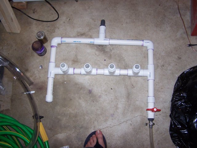
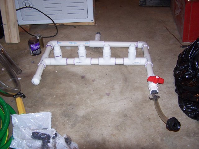
So, this iteration accomplishes all those things. First off, I built the bottom manifold. This one has four male threads for each leg of the filter to screw onto. This way if I ever need to, I can take them off individually without having to cut anything. I'm tired of cutting things apart and having to rebuild them because I glued absolutely everything together. You can also see the hose pigtail with a garden hose fitting on it for priming the system. All I need to do is attach the garden hose, open the ball valve, and it will purge all the air from the bottom up.
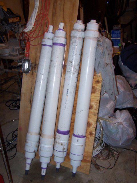
Here are the legs of the filter. Each one is 4" PVC filled with lava rock. 1" FPT on one end, 1" male hose barb on the other.
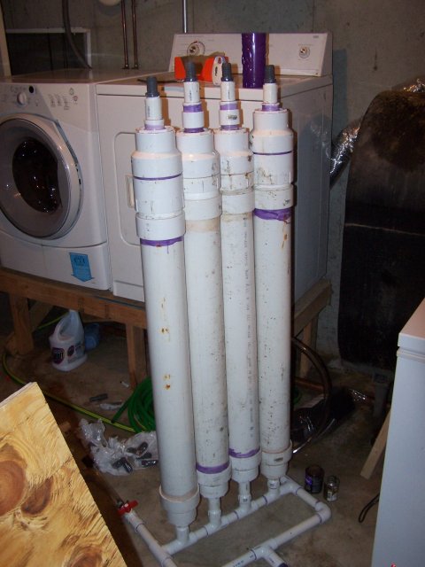
Here they are attached to the bottom manifold
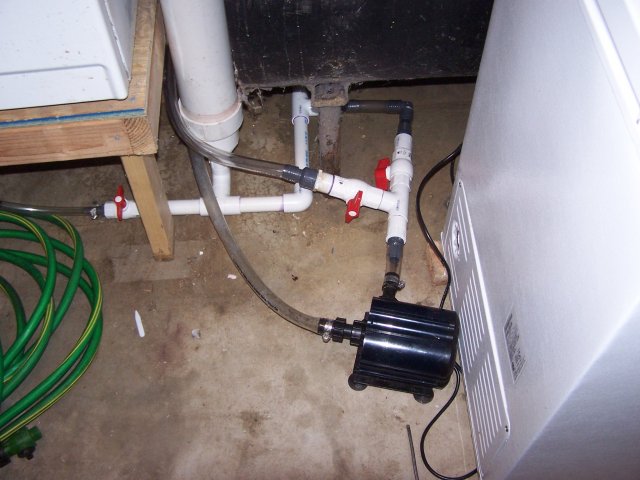
Here is the network with the pump attached. The clear line comes in from the pond, into the pump, and out. Straight out of the pump goes into the filter. If I close that ball valve and open the other one, that sends water up into the top of the filter and down through (essentially backwards from normal operation). There is a hose pigtail on the bottom, so if I open that ball valve, I can backflush the system. Additionally, now that I have individual ball valves on each leg, I can backflush them one at a time, getting a lot more flow through each one, hopefully doing a better job.
The clear line here not attached to anything is the backflush line. That will be attached to the T right there, which needs a ball valve after it. That way I can close it so it will actually backflush instead of just bypassing the filter and going back to the pond. You can also see the ball valves on each filter leg, right before going into the exit manifold. I used hose barbs rather than threaded fittings here just to make it easier to take it apart if I need to.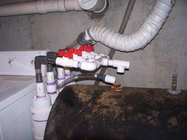
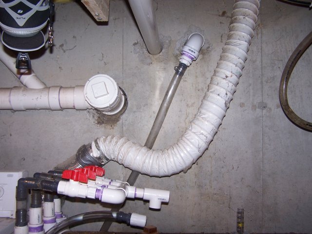
Here you can see the in/out through the basement wall. The holes used to be for the oil tank fill pipes, but they were relocated. The one hooked up is the supply, the other one obviously needs to be cut, and will be the return to the waterfall.


1. I wanted to move the pump down to the floor. Having it high up on the shelf made it practically impossible to prime.
2. I wanted valves on each leg of the filter to close each one down independently.
3. I wanted a backflush loop to clean it out periodically...ties in with #2.
4. I wanted an easy way to prime it with a hose.
So, this iteration accomplishes all those things. First off, I built the bottom manifold. This one has four male threads for each leg of the filter to screw onto. This way if I ever need to, I can take them off individually without having to cut anything. I'm tired of cutting things apart and having to rebuild them because I glued absolutely everything together. You can also see the hose pigtail with a garden hose fitting on it for priming the system. All I need to do is attach the garden hose, open the ball valve, and it will purge all the air from the bottom up.


Here are the legs of the filter. Each one is 4" PVC filled with lava rock. 1" FPT on one end, 1" male hose barb on the other.

Here they are attached to the bottom manifold

Here is the network with the pump attached. The clear line comes in from the pond, into the pump, and out. Straight out of the pump goes into the filter. If I close that ball valve and open the other one, that sends water up into the top of the filter and down through (essentially backwards from normal operation). There is a hose pigtail on the bottom, so if I open that ball valve, I can backflush the system. Additionally, now that I have individual ball valves on each leg, I can backflush them one at a time, getting a lot more flow through each one, hopefully doing a better job.

The clear line here not attached to anything is the backflush line. That will be attached to the T right there, which needs a ball valve after it. That way I can close it so it will actually backflush instead of just bypassing the filter and going back to the pond. You can also see the ball valves on each filter leg, right before going into the exit manifold. I used hose barbs rather than threaded fittings here just to make it easier to take it apart if I need to.

Here you can see the in/out through the basement wall. The holes used to be for the oil tank fill pipes, but they were relocated. The one hooked up is the supply, the other one obviously needs to be cut, and will be the return to the waterfall.


